Our research group has taken the lead in inventing a number of designs for Penning traps to replace the hyperbolic trap design that was used in earlier days. In so doing we showed that carefully selected trap geometries would produce a very high quantity Penning trap potential, while at the same time allowing the trap to form a calculable microwave cavity, or allowing the trap to capture exotic particles (like antiprotons) which were not well localized when they arrived at the trap. Most of the new trap designs are also much easier to fabricate. After introducing the trap designs of interest there is a brief description of what it means to have an "orthogonalized" Penning trap design.
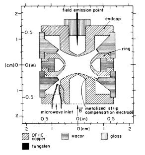
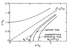
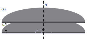
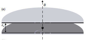
Orthogonalized Hyperbolic Penning TrapWe invented this trap design to keep the axial frequency of a trapped particle from changing when the potential on the compensation electrodes is tuned to make the trapping potential more harmonic. It was the first of a series of trap designs (below) which made the axial oscillation frequency and the compensation tuning to be orthogonal. The axial oscillation is vertical for the trap shown to the right, along the direction of the vertical magnetic field. A relaxation calculation was used to find the ideal orthogonalized geometry, and to calculate the detection efficiency and damping that this special geometry would provide. This trap geometry was used, for example, for the MIT Penning trap (now at Florida State) with which a large number of the most accurate ion masses have been measured. The second figure compares the optimal relative geometry to others that have been used. |
  |
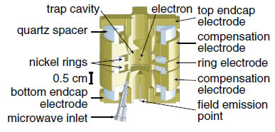
Orthogonalized Cylindrical Penning TrapWe invented the cylindrical Penning trap for the one-electron quantum cyclotron measurements (discussed above) which resulted in a 3 parts in 1013 measurement of the electron's magnetic moment in 2008. The first demonstration of such a trap showed that its orthogonalized trap design (which makes the axial frequency of an electron to be largely independent of the compensation potential that is tuned to make the trap more harmonic) made it possible to observe and manipulate a single electron in this environment. The radiation field that a centered electron experiences is determined by the boundary conditions of the surrounding trap electrodes - a high quality cylindrical microwave cavity cavity with familiar TM and TE radiation modes - making it possible to calculate the interaction of a trapped electron and the radiation field. We use this cavity to inhibit the spontaneous emission of synchrotron radiation from the trapped electron's cyclotron motion by a factor as large as 200 or more. This gives us the time that we need to fully resolve the quantum structure of the electron's cyclotron motion. |
 |
Open-Access Orthogonalized Penning TrapThis open-access orthogonalized Penning trap was invented to allow us the axial access needed to capture antiprotons which were not well localized as they arrived a our trap, at the same time as providing a environment for one trapped antiproton that allowed us to show that the antiproton and proton have the same q/m magnitude to better than 9 parts in 1011 (90 ppt). After the antiprotons are captured and electron-cooled, their number can be carefully reduced until only one remains.We have held one antiproton for months in such a trap. A careful choice of the relative heights of the hollow ring electrodes gives the desired "orthogonalized" behavior, in which the axial frequency of the antiproton is largely independent of the compensation potential that is tuned to make the trap more harmonic. |
 |
Planar Penning TrapAll of the trap electrodes for a planar Penning trap are deposited on the surface of one plane. This trap design (unlike other designs discussed below) is potententially scaleable to many traps with their electrodes in the same plane, with possible electronic coupling and detection circuits microfabricated into the trap plane (or one that is parallel). No effort to observe a single electron loaded into such a trap has succeeded so far. Our extensive 28 page report argues that the planar trap designs attempted so far are designed in a way that makes it nearly impossible to observe a single electron stored within. We identify new optimized designs for planar traps that reduce the amplitude dependence of the crucial observed oscillation frequency. Our theoretical study of planar Penning traps builds upon long history of introducing new trap designs. One challenge is that there are no "orthogonalized" trap designs possible for planar Penning traps. We show how to optimize ideal planar traps, and we introduce enclosed planar Penning traps, covered planar Penning traps, and mirror-image planar traps. |
 |
| Variations: | 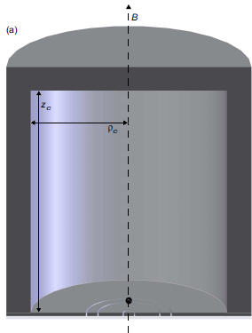 |
 |
 |
| Enclosed Planar Penning Trap | Covered Planar Penning Trap | Mirror-Image Planar Penning Trap |
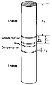
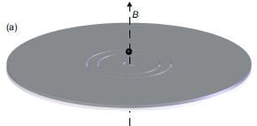
An ideal Penning trap is a spatially uniform magnetic field directed along the symmetry axis of an electrostatic quadrupole potential. The potential could be realized by placing conducting electrodes along any two of the hyperbolic equipotentials of the desired quadrupole potential (e.g. "endcap" and "ring"). Below V0 is the trapping potential - the potential difference between the endcap and ring electrodes, while d is a characteristic size of the trap.
| B = (0,0,Bz) | 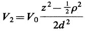 |
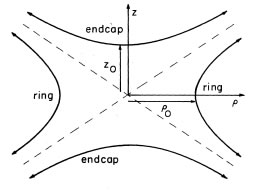 |
| Magnetic field in z direction | Ideal quadrupole potential is axially symmetric about the z axis |
Equipotentials of the ideal quadrupole potential go out to infinity |
There are two problems. First, it is not possible to extend electrodes to infinity. Second, real trap electrodes are not perfect. The two problems together means that the potential near the center of a real trap always has potential terms added to the desired quadrupole potential, V2.
 |
Reflection symmetry as z goes to -z is assumed here |
For the most accurate measurements with one particle in the trap it is necessary to reduce the size of the leading departure from the desired quadrupole potential. This make the trap more harmonic in that a centered particle sees a harmonic oscillator potential that goes as z2. In other words we need to make the coefficient C4 to be as small as possible.
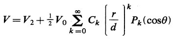
In all of the trap designs above the coefficients Ck can be changed by tuning the compensation potential Vc on additional electrodes that are added to the endcap and ring electrodes.
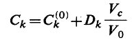
The coefficients Ck(0) and Dk depend only upon the relative geometry of the trap electrodes - not upon applied potentials. The trap is made more harmonic by tuning Vc to Ck close to zero.
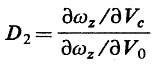
Unfortunately, tuning the compensation potential Vc typically also changes the axial frequency ωz of the trapped particle as well. It is very hard to tune a trap when the axial frequency changes with every change in the compensation potential. In addition, the extremely stable axial frequency that is generally needed is difficult to attain when this frequency changes in proportion to the voltage noise in the tunable compensation potential. An "orthogonalized" Penning trap is one for which the relative electrode geometry is chosen to make
D2 = 0.
This makes the the axial oscillation frequency of a centered particle to be independent of the tuning of the compensation potential. The coefficient D2 gives the relative sensitivity of the axial oscillation frequency to the compensation and trapping potentials.
A more detailed overview is in the original papers linked to above, and in the later review by Brown and Gabrielse.
© 2015 - Last Updated: 08/30/2018 - Disclaimer